RoadTest: Rohde & Schwarz Oscilloscope Kit RTM3K-COM4
Author: snidhi
Creation date:
Evaluation Type: Test Equipment
Did you receive all parts the manufacturer stated would be included in the package?: True
What other parts do you consider comparable to this product?: The other oscilloscopes in this price range are from Rigol, Siglent, Keysight Technologies, Tektronix, Hantek and OWON.
What were the biggest problems encountered?: To access the online content for the R&S oscilloscopes you have to make a login which is verified by the R&S customer care and only then the login is valid.
Detailed Review:
This is a detailed review of the Rohde & Schwarz Oscilloscope Kit RTM3K-COM4Rohde & Schwarz Oscilloscope Kit RTM3K-COM4
Motivation for the Road-Test
I have worked with many diverse oscilloscopes in my job profile as an electronics engineer. All thanks to the research institute where I am located. A few of them to name are LeCroy WaveRunner 610Zi, Tektronix MSO/DPO70000 series and Keysight Serie 3000T and ofcourse Rigol (personal). I have also laid my hands on Rohde & Schwarz power supply and R&S signal generator but not yet on one of their scopes. Therefore, this road test is interesting opportunity for me to evaluate the Rohde & Schwarz oscilloscope which is available at a good price point.
I bought my first personal oscilloscope Rigol MSO 4034 with 500 MHz Bandwidth three years ago in 2015 when I started tinkering with electronics at home beside my day job. To buy this oscilloscope I spent almost one year investigating different scope options and their pricing (well... who doesn't like a good deal) and saving money for last 5 years. I spent most of the time analyzing the real BW of scopes, what are the upgrade options as many scopes are locked only in software and not in hardware, what drives the pricing and the state of art electronics used in oscilloscopes, the quality of probes and their impedances, noise floor levels in the oscilloscope hardware etc. In the end I pushed my budget from 3000 Euros to 7000 Euros and got my first oscilloscope because this is an investment for a life time. I think investing in good measurement instruments is paramount specially legacy devices such as multimeter, oscilloscope and a good soldering station.
In this road-test; I put all my investigations to use so other future buyers can deeply analyze what they are paying for and what they get is a trade off which is balanced very finely by the oscilloscope industry.
There is a famous joke in my lab that one could buy a car for the same price as a scope but the oscilloscope is worth it. And I don't own a car. 
Table of Contents
I want to thank Rohde & Schwarz Oscilloscope Kit RTM3K-COM4 and element14 for selecting me for this Roadtest.
The current revolution in oscilloscope pricing can be attributed to how cheap the ADCs have become. R&S RTM3004 is a high performance scope placed at the border of the economical range. Such devices are necessary for analog and even digital engineers. They can solve many issues which cannot be debugged in software only mode.
Oscilloscopes are the Ferrari of the electronics debugging world.
To begin with one can argue, as to why do we need an oscilloscope? Many engineers today are happy working with a multimeter and "printfs". But adding an oscilloscope to the workbench can open a whole new world of signal measurements which cannot be done with a simple instruments. A good scope is handy when measuring fast and clocking signals, ripple and noise measurements in power devices, debugging bus communication (I2C, CAN, RS232), signal FFTs and list is infinite. They are a valuable debugging tool to measure outputs at the analog end and on pcb-side. I encountered many problems where it made me realize that the origin of the issues may not always be software and tweaking around with a probe on the hardware can give valuable insight.
As quoted by Wikipedia
Oscilloscopes are used to observe the change of an electrical signal over time, such that voltage and time describe a shape which is continuously graphed against a calibrated scale. The observed waveform can be analyzed for such properties as amplitude, frequency, rise time, time interval, distortion and others. Modern digital instruments may calculate and display these properties directly. Originally, calculation of these values required manually measuring the waveform against the scales built into the screen of the instrument. Other signals (such as sound or vibration) can be converted to voltages and displayed.
Interesting Historical Facts About Oscilloscopes
Karl Ferdinand Braun was a German inventor, physicist and Nobel laureate who invented the first cathode ray tube oscilloscope in 1897. Braun was born in Fulda, Germany, and educated at the University of Marburg and received a Ph.D. from the University of Berlin in 1872.
Reference: Oscilloscope Fundamentals Rhode und Schwarz Document
He applied an oscillating signal to horizontal deflector plates and a test signal to a vertical deflector in a phosphor-coated CRT. The plates produced transient plots of electrical waveforms on the small phosphor screen. This invention evolved (Figure 2) into a measurement instrument and was gradually improved over the next 50 years. The advancement by engineer Howard Vollum in 1947 that made the oscilloscope a highly-useful instrument, allowed a trigger to control the sweep function for the first time. Reference
The era of digital oscilloscopes began in the 1980s with the rise in fast ADC and memory recording integrated circuits. And combined with the advancement in the waveform display screens the Oscilloscopes have taken over the world.

Reference: Growth Time-line of the Oscilloscopes
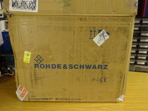
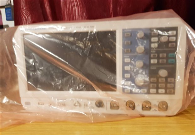
The Rohde & Schwarz Oscilloscope Kit RTM3K-COM4Rohde & Schwarz Oscilloscope Kit RTM3K-COM4 was delivered in a big box well secured with cushions as packing material. Rohde & Schwarz being a German company I was a bit surprised that the scope came from the U.S. And after minor issues with the import authorities at the German border and them asking the same question to me (that why I imported a German brand product from the U.S. (yeahh logic..)) and help from the Rohde & Schwarz guys the device landed on my doorstep. R&S and element14 did pay the import taxes so I did not have to pay any extra money to the authorities . The packaging is very important when such sensitive electronics has be delivered half way across the globe and R&S did a good job.
| {gallery} Unboxing RTM3004 RTM3K-COM4 |
|---|
Fig 1: The Delivery |
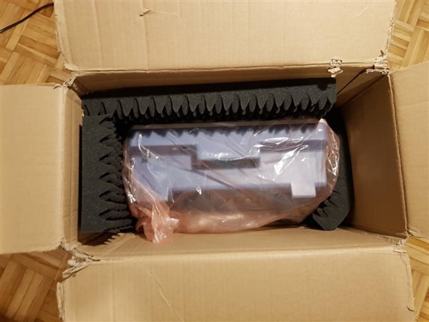
Fig 2: The Opening Ceremony |
Fig 3: The Opening Ceremony |
Fig 4: The Unboxing |
Fig 5: The Unboxing |
Fig 6: The Unboxing |
Fig 7: The RTM3004 RTM3K-COM4 |
Fig 8: The RTM3004 RTM3K-COM4 |
Fig 9: Power Cables |
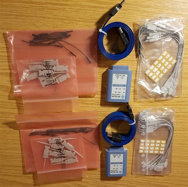
Fig 10: The Probe Set Delivered |
Fig 11: The Probe Set |
Fig 12: The Digital Probe Set |
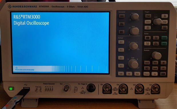
Fig 13: The RTM3004 RTM3K-COM4 First On |
Fig: Unboxing video and Description of RTM 3004 oscilloscope
After a quick software update from R&S I was ready to go
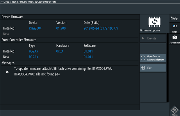
Fig: Updated Software
A list of license available with the oscilloscope. As mentioned already the Spectrum Analyzer license will be available in September and was not given together with the device.
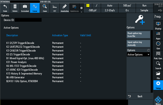
Fig: List of licenses available with in the pack
The first operation of the RTM3004 RTM3K-COM4 was quite different. If you are used to using oscilloscopes from Keysight or Tektronix (like me) then there can be a small kick  in the start. I had felt the same kick when I had started working with LeCroy. I needed sometime (like half a day) to figure the control panels out and it was smooth sailing after that. Rohde & Schwarz have their own unique philosophy and identity for their each line of devices. This oscilloscope has no operating system but uses the an App button to access all its features.
In my experience with the Rohde & Schwarz devices and instruments upholds its quality and robustness over pricing. I have used R&S 25 years old devices in my lab still functional as good and with minimum repairs from the time they were bought.
The RTM3004 from Rohde & Schwarz is a mixed signal oscilloscope which includes logic and protocol analysis together with analog waveform visualization. Signal integrity measurements are key for hardware engineers and signal content analysis for bus protocols can be helpful to software engineers while troubleshooting. This oscilloscope has four analog channels and 16 digital channels where both analog and digital signals can be acquired synchronously and correlated in time.
List of features in RTM3004 RTM3K-COM4
The RTM3004 has quite some legacy to uphold and is a perfect answer if one is looking for an oscilloscope in 1 GHz Bandwidth range with high sampling rate and many other classical features integrated in one device.

Fig: A quick guide for RTM3004 RTM3K-COM4
A quick feature contrast of RTM3004 with other available with RT Series R&S oscilloscopes
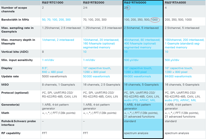
Fig: Comparison Chart
A quick comparison of the oscilloscope with its competitors reveals that RTM Series does fairly well although it is priced lower cheaper for its range.

Fig: Specifications Comparison
A more detailed look into the competition with other featured oscilloscopes with respect to R&S RTM 3004. The other oscilloscopes lie in the similar price range and specifications range as the RTM 3000. I have marked the most important parameters in red for comparison.

Fig: Tektronix vs R&S RTM 3000
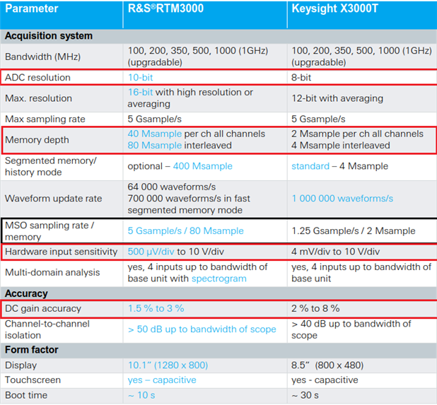
Fig: KeySight vs R&S RTM

Fig: LeCroy vs R&S RTM
A quick comparison of the Rigol MSO 4034 and RTM3004 RTM3K-COM4
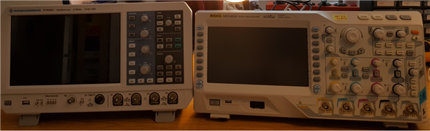
Fig: Built Comparison between Rigol MSO4034 and RTM3004
| Comparing the different oscilloscopes by weight | Weight Comparison |
|---|---|
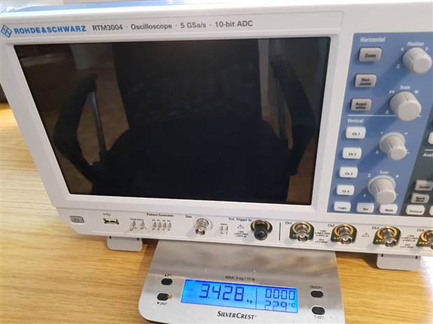 | RTM3004 RTM3K-COM4 with 1GHz BW
3.4 Kg |
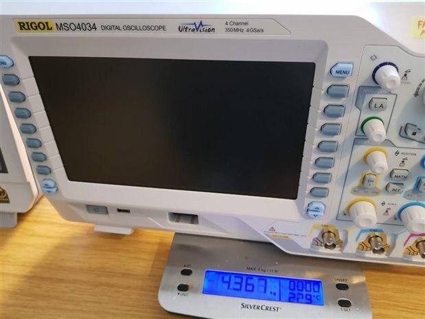 | Rigol MSO 4034 with 500 MHz BW
4.3 Kg |
A quick look at the front panel of the oscilloscope and its features. One key feature here is that there is only one control for all the 4 channels as compared to traditional oscilloscopes where each channel has a separate control button. The channel selection is well color-coded but can get confusing at times. The removal of other 3 channel controls was done to increase the screen size it seems.

Fig: Front Panel Description

Fig: 16 Logic Analyzer digital channels on the side panel
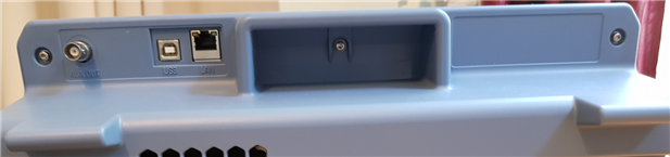
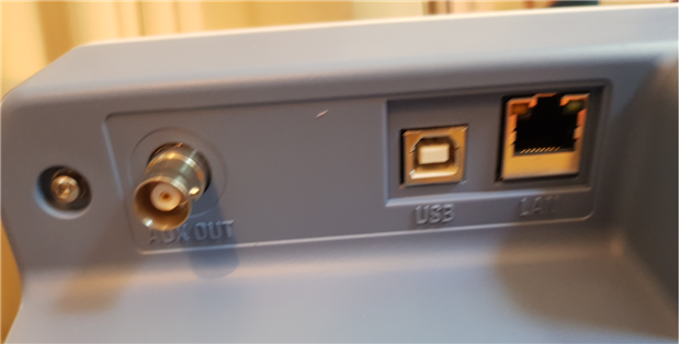
A detailed look to the side panels and ports of the oscilloscope
| {gallery} Complete look of R&S RTM3004 |
|---|
Fig 1. Back Panel |
Fig 2. USB and LAN Support |
Fig 3. Extra Power Control with Lock Control |
Fig 4. Fan on the side |
Fig 5. |
 A few negative points that I did not like about the design of the oscilloscope

There are 2 legs at the front of the oscilloscope which are not very sturdy and seem to be made of cheap plastic. They also don't have a rubber padding as well. It happened few times that the scope became unstable at the table. It was quite annoying.
There is no handle to carry the oscilloscope but only a gap like thing which is support to act as a carrying support. This increases the risk of dropping the equipment on the floor. It is not a good design and a handle is more sturdy and secure. Not a fan of this either as I was moving the scope many times between my lab and home. Bring back the handle!
Here we are going to look into the basic block diagram of an oscilloscope and fit it to the RTM3004 and what this scope offers in terms of internal ADC, vertical system, horizontal system acquisition and processing.
A detailed list of the specifications of the oscilloscope is given here and have been verified in this road-test. A quick look at its competitions gives an idea of the pricing vs quality where RTM3004 is a winner.
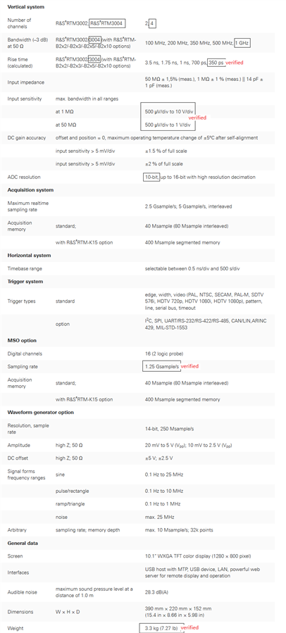
Fig: Specifications Overview

Fig: Simple oscilloscope Block Diagram

Fig: Vertical Specs of RTM3004

Fig: ADC Sampling how it works
To avoid any aliasing the Nyquist rule should be followed and the sampling rate should be at-least 2x higher than the signal frequency.

Fig: Horizontal system working Diagram

Fig: How record length is determined

Fig: RTM 3004 Horizontal System specs Ref

Fig: RTM 3004 Acquisition System specs Ref
Record length = Sample Rate x Time Scale x Number of Divisions (10)
| Sampling Rate | Time Scale X Number of Div (10) | Record Length |
|---|---|---|
| 5 GS/s (ch1) | 100 ns/div | 5K samples |
| 2.5 GS/s (ch1 and ch2) | 100 ns/div | 2500 samples |
| 5 GS/s (ch1) | 100 us/div | 5M samples |
| 2.5 GS/s (ch1 and ch2) | 100 us/div | 2500 Ksamples |
Hence one can see here that the record length is dependent on the timescale and the sampling rate. The higher the sampling rate the better the output and indeed higher the price!!
The advantages of higher sampling rates are
A deep memory allows for capturing longer time periods while maintaining high resolution (fast sampling rate). The zoom in capability into the signal is also increased. The memory depth determines the maximum possible record length for one acquisition.

Fig: RTM 3004 Memory depth vs record length
To put it in a simple manner; using the maximum record length of 40Msamples/sec at 5GS/sec (full sampling rate) with the above formula the oscilloscope will capture a signal 8 millisecond in length.
A combination of long record length with fast waveform capture rate allows to search for transients in the signal such as jitter and glitches. RTM 3004 offers much higher memory depths as compared to its competitors and this sets it above the others.

Fig: Comparing memory depths with other oscilloscopes

Fig: Memory Segmentation Specification for the RTM 3004
Here is a short description of the different memory types and their sizes with functionality in the oscilloscope. The 512 Mbyte Flash memory on main board stores the device ID, the instrument firmware, the factory calibration/alignment data and the current alignment data. It also stores all the instrument settings, user data and current state of the oscilloscope.
Hence the user data or the settings are not deleted after power-off. So one can turn off the power and come back later are resume measurements from where you left.

Fig: Types of memory
This oscilloscope has also a Secure Erase Feature which allows the user to clean the internal flash memory using their specific Sanitization Procedure for any security reasons. This is a specific Instrument Declassification procedure to allow the safety of user data for high secure environment. After declassification self alignment must be done.
The RTM 3004 came with four 500 MHz passive probes RT-ZP10 with the probe rise time of 700 ps and input capacitance of 9.5 pF.

Fig: 500MHz BW passive probe

Fig: The Probe RT-ZP10 Kit
Each probe must be adjusted for low frequency LF compensation and for high frequency HF compensation. When the probe is connected to the input LF compensation must be done to match the probe cable capacitance to the input scope capacitance. A poorly compensated probe can show distorted waveforms.

Fig: LF Probe Compensation
HF Compensation Compensation is not a must but should be done if faster signals are being measured close to the 700 ps rise time range.
Here is a list of devices that were used for measurements and experiments during this road-test. A brief idea of these devices and their functionality have been presented.
Bandwidth is the most important specification when it comes to selecting the right oscilloscope for analog or digital measurements.
The oscilloscopes have either a Gaussian response GR(=< 1GHz) or maximally-flat frequency response MFFR(>1 GHz). The Gaussian response exhibits a slow roll-off at approx 1/3rd the -3dB frequency. And the maximal flat frequency response shows a flatter in-band response with sharp roll- off near the -3bB frequency. A scope with Gaussian response (GR) has a faster rise time than the one with Maximally-flat frequency response (MFFR) for the same bandwidth specification but the MFFR can measure more accurately as they donot attenuate the in-band signals. The GR attenuates the out-of-band signals and hence eliminates the high frequency components in the signal which cause aliasing.

Fig: Gaussian Frequency Response
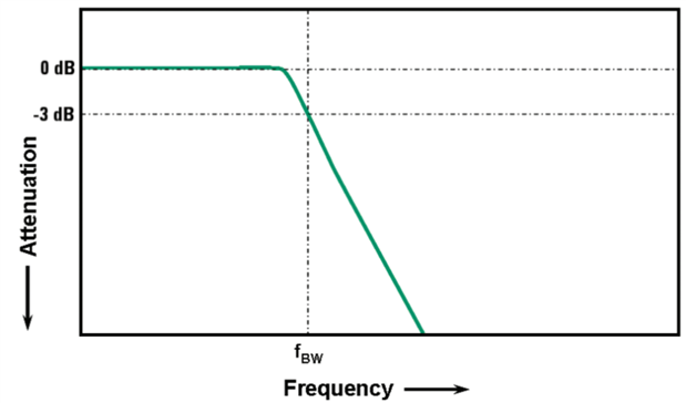
Fig: Maximally-flat frequency Response (MFFR)
Further calculations and details are in the blog here
The lowest frequency when the input signal is attenuated by 3dB defines the scope bandwidth and this has been tested here with the signal generator. At -3dB the signal attenuation leads to approx -30% amplitude error which can also been seen in the results. This concludes that one cannot accurately measure signals at the edge of the scope BW (1 GHz). I measured this in the following experimental setup. The tests can be found in the blog here
The scope bandwidth defines the rise time of the signals it can measure. Although one must understand that the scope's rise time is not the fastest edge that it can accurately measure but the fastest edge it will try to reproduce if the input signal has a thematically infinitely fast signal with rise time = 0ps. This has been tested in this blog here by inputting a pulse edge which is 16 times faster than the theoretical rise time of the RTM-3004 oscilloscope. The experimental setup can be found here
Internal noise of an oscilloscope can be a limiting factor when smaller and highly sensitive signals are to be measured. A scope with low noise or high dynamic range to look into small signals or find small changes in large signals. For each measurement the oscilloscope should be configured precisely by setting its vertical sensitivity (volts/division) and horizontal time base. This can be achieved quickly if one is aware of the noise floor of the scope. There are circuits where the system circuit noise is designed to be low. If such circuits are measured using a scope of higher internal noise the results will be distorted as there is an addition to the signal noise level from the measuring device (oscilloscope). Then one realizes that this particular scope is not a valid device for this particular measurement and one needs to chose another oscilloscope.
Detailed list of contents in the Noise Measurements Blog
Please read further here
Please read further here
Please read more here
Please read more here
Further detailed tests with the R&S RTM 3004 have been presented in the blog here Noise Measurements
In this part of the blog; experiments were designed to test the different protocols and bus decoding functions offered by the RTM3004 oscilloscope. Please read the following blogs for detailed results
Experiments with Logic Analyzer
A quick look at the bus types which can be visualized and decoded in the RTM3004

Fig: Digital Protocol Evaluation
Further experiments have been done in the blog here
Here, I have done some basic measurements of the waveform generator and its capabilities. They are not in much detail but a basic overview of this feature offered by R&S RTM 3004 oscilloscope. Please read further here.
In this blog; I have re-done the measurements with the development board TPSM84A21 Power Module DC/DC Converter and measured the ripple and power efficiency parameters with RTM 3004 oscilloscope.
The results can be found here.
The results can be found here.
The results can be found here.
The results can be found here.
The results can be found here.
The measurement setup and results can be found here.
Rhode & Schwarz allows full control and setting up the oscilloscope in real time via a browser window. Once the scope is setup in your work/home network it can be easily controlled and data can be saved online. It also allows access to live screen and Front Panel. More details on this is in the blog here.
Using these references all the tests done in the Road-test can be reproduced and tested independently
In short the R&S RTM3004 truly stands-by all its specifications and is an 8 instruments in one device without compromising in the integrity of the a good oscilloscope (analog-wise). As I saw in many tests it performs better than as mentioned in the data-sheet. And with a number of software options to chose from elevates the R&S RTM 3004 instrument from a simple oscilloscope to a complete Measurement System. Added features of logic analyzer, spectrum analyzer fulfill the needs of an analog and digital engineer. The RTM 3004 is very well placed in the medium price range with good specifications.
In conclusion, this was quite a learning road-test for me and a challenging one to achieve. I have managed to fulfill all the promises in made in the road-test application for the RTM 3004. All the measurements and results have been published here so the methods can be used to reproduce the tests by the community.
Note: This road-test has officially ended


Top Comments
Great start to the review and thank you for all your time and efforts!
I'll pass your feedback on the front feet and lack of a handle.
-Rich@RohdeScopes
Thank you Rich for your efforts as well.
You have been a great support to the developers and fast in solving the issues.
My review will be on-line soon as well.
Cheers
SNidhi
Nice start to your review of this beautiful scope. I noticed that there are a lot of "under construction" disclaimers so no one mistakes this a final review.
From what I can see you are doing…