


Hello all
Not posted anything for some time but the project did not stalled at all.
What I have done so far:
- RaspberryPi + RTC + Display&Control assembled, installed and configured (shown in previous posts, 1, 2, 3)
- build the power board
- build control board for power LED and RGB strip
- assembled charging modules for Li-Ion batteries
- connected together all the above
In the following video you'll see a demo of almost all hardware used for Cybernetic Computer Interface project, only headphones, microphone and some wiring are missing. After that, if still interested, you can see modules description.
Power board
Power board should be able to supply reliable power to RPi and all peripherals.
RPi, sound card, WiFi dongle and SD Card reader need 5V, power LED and RGB strip need 12V.
For 5V rail I used Pololu 5V, 5A Step-Down Voltage Regulator D24V50F5. May be a little overkill for this application but I like to have some reserve. Besides, keeping a lower load on the converter the drop-out voltage is lower than for higher load, around 1V. If I had used a converter rated for lower current output, 2Amps for example, the load would been higher and drop-out voltage also higher, which is less efficient for a battery powered application.
For 12V rail I choose Pololu Adjustable Boost Regulator 4-25V, set at 12V.
As power source I used four Li-Ion cells, recovered from a dead laptop, connected in pairs and then in series. Each cell is 2200mA/3.6V so in theory when fully charged this power pack should supply 8.2V/4400mA.
To charge the pairs of cells, I used two USB LI-PO BATTERY CHARGERS by Olimex. I choose this solution because I cannot find a 2 cells Li-Ion charger with balancing, small enough to be integrated in my project. Charging time is very long though, each charger can supply only 470mA.
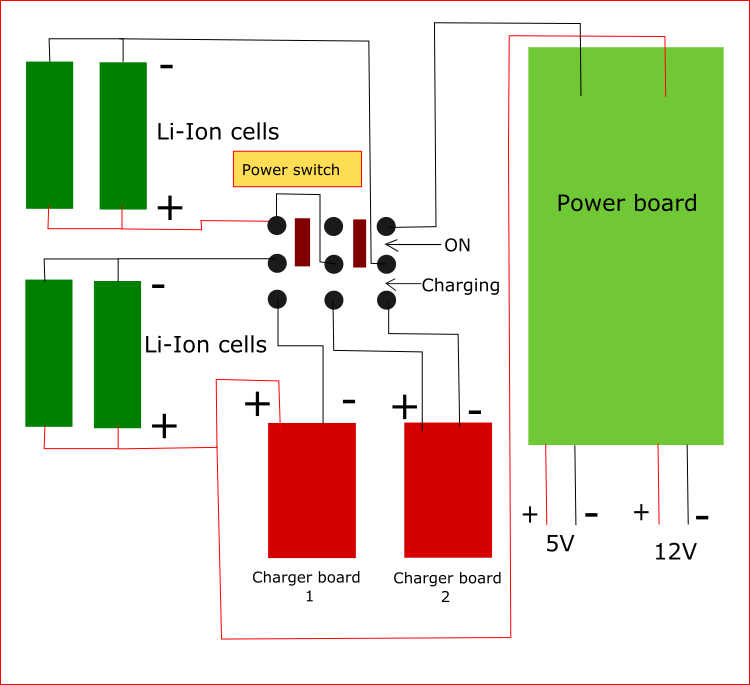
Here is the schematic of batteries, chargers and power board connections:
Power for USB components
Most peripherals gets their power and communicate over USB. Because of design constrains, these modules cannot be connected directly to RPi USB ports, so an USB Hub has to be used.
I choose a seven ports USB Hub and hack it to suit my needs.
I remove the Hub enclosure and I cut the power wire (positive (+)) from the cable between RPi and Hub, so RPi won't be back powered through this cable, only data will flow. I'm not sure if this is needed, I thought its safer this way.
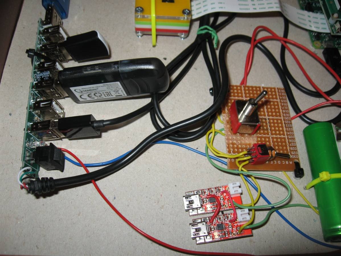
Then I powered the Hub with 5V coming from power board, red and blue wires in pictures below.

LEDs control board
I build it on a piece of perf board and consist in four BC639 medium power NPN transistors and current limiting resistor for connection to RPi GPIO pins.
RGB LED strip is connected directly to 12V rail and the 1W power LED have a current limiting resistor.
Light intensity for RGB LED strip and power LED is controlled using PWM.
For PWM I used GPIO pins 12, 16, 20 and 21 - BCM notation. To generate PWM on these pins I used RPi.GPIO library.
I tried also RPIO library but so far it is not working on RaspberryPi ver.2
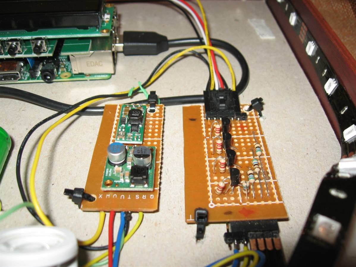
Here you can see power board on the left and LEDs control board on the right.
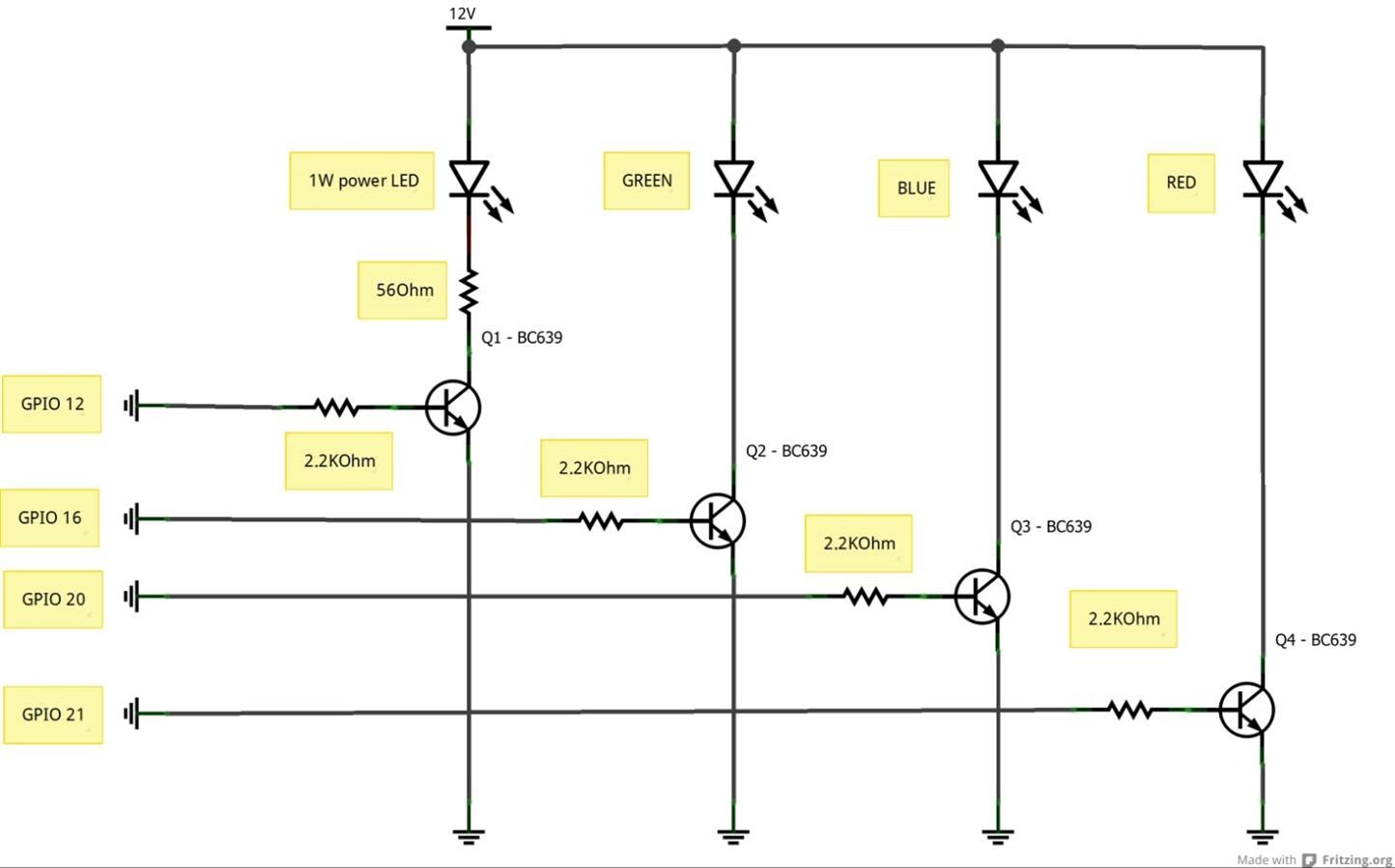
And the schematic:
The next post will be dedicated to the python code that made the whole thing tick.
All the best
-=Seba=-


